HOW TO CHOOSE THE RIGHT MEDICAL CONNECTOR

The design of medical devices is highly dependent on an efficient underlying electronic interconnection system. Therefore, it is very important to design and select the right medical grade connectors.

In the design of medical devices, engineers of connector manufacturing company  will face many challenges and extremely complex choices that will not happen in other industries. Medical devices need to have enough durability and reliability, and the use conditions are often very strict. The influencing factors include liquid, disinfection and sterilization, physical interference and electromagnetic interference, as well as extremely high insertion and extraction times.

These medical devices are highly dependent on the effectiveness of the underlying electronic interconnection system. Connector design is an integral part of the design process, and it is very important to select the right connector.

Choose the Right Connectors for Medical Devices

The first consideration for engineers is to decide whether to use off the shelf connectors, hybrid versions, or custom solutions. Off the shelf products are already on the market and there are many configurations to choose from. The engineering investment and tooling investment of this kind of products are often low, but the lead time is very long, and the unit cost is also high. Hybrid provides customized overmolded features on existing connectors. Compared with the off-the-shelf products, this kind of products improve the performance and aesthetic value, and compared with the fully customized connector, its design cost and engineering cost are lower, but the lead time is also longer.

The custom medical connector is a product designed and manufactured for specific customers, equipment or applications. Using custom connectors will make it easier to integrate components or electronic components and add marking or logo. The initial investment in engineering and mold making is generally high, but depending on production, such solutions will be more cost-effective in the long run.

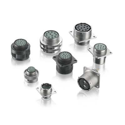
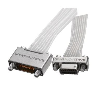
The ready-made connector with customizable package shape clearly identifies which input port can be connected with.

Consider Each Application

In many cases, customized or hybrid solutions are more popular than off the shelf solutions, especially when there are some special considerations.

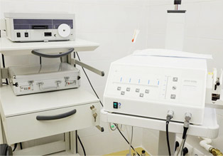
For example, in a disposal room where dozens or more different cables and connectors are used at the same time, medical personnel will face the risk of misconnection of cables and equipment. The ready-made connector can be equipped with different colors of plastic clad housing, and this hybrid product can clearly indicate which connector to connect with which device.

When the patient’s heart stops, the equipment used by the patient usually needs to be able to withstand 5000-8000 volts defibrillation pulse. In this case, insulation, spacing, material and air gap can be customized to meet the specific needs of the application.

Other examples of custom solutions include connectors designed to prevent incompatibilities at insert time. Or, considering human engineering, the ideal medical interconnection system needs to be large enough for the intended user to operate easily and insert intuitively.

Understanding the Process

In the case of hybrid or customized medical connector, the design, mold and manufacturing process generally takes four to eight months. At the early stage of the design process, the team should clearly define the requirements, including electrical (voltage, cardiac shock, bandwidth / data rate, etc.), mechanical (cable diameter, human engineering characteristics, expected bending life, expected insertion force and pull-out force, etc.), and environmental (sealing and intrusion protection, cleaning, disinfection and sterilization, etc.).

Once the specifications have been established and the design work agreed upon (including the mock up), prototyping can begin.

When choosing hybrid or customized mil spec connectors, it is very important for all related units to cooperate with each other. In this way, the medical equipment that can perform well in the field and meet all the mechanical and electrical requirements (including connectors and cable components) can be produced.

FIVE COMMON FEATURES OF USB CONNECTOR

USB, the abbreviation of universal serial bus in English, is an external bus standard, which is used to regulate the connection and communication between computers and external devices. It is an interface technology applied in the field of PC.

Universal serial bus (USB) is a new data communication mode which gradually replaces other interface standards. It was jointly developed by Intel, Compaq, digital, IBM, Microsoft, NEC, Northern Telecom and other computer companies and communication companies in 1995, and gradually formed industry standards.

As a kind of high-speed serial bus, USB bus’s extremely high transmission speed can meet the application environment requirements of high-speed data transmission, and the bus also has the advantages of simple power supply (bus power supply), convenient installation and configuration (plug and play and hot plug are supported), simple expansion port (127 peripherals can be expanded at most through the hub), diversified transmission modes (4 transmission modes), as well as the advantages of good compatibility (downward compatibility after product upgrade).

Since its introduction, universal serial bus has successfully replaced serial port and parallel port and has become one of the standard expansion interfaces and necessary interfaces for a large number of computers and intelligent devices in the 21st century. Now it has developed to USB version 3.2. USB has the advantages of fast transmission speed, convenient use, hot plug support, flexible connection, independent power supply, etc. it can connect a variety of peripherals such as the keyboard, mouse, large-capacity storage device, etc. the interface is also widely used in smartphones. The interaction between intelligent devices such as computers and external data is mainly based on network and USB interface.

1. Polarization

The USB connector can only be nominally inserted in one way. It is possible to force a wrong connector, but this can cause damage to the device.

2. At least four contacts

All USB connectors have at least four contacts (some USB models may have five, USB 3.0 connectors or more), which are used for power, ground and two data lines (D + and D -). The USB connector is designed to transmit 5V up to 500mA.

3. Shielding

The USB connector is shielded, so it provides a metal shell that does not belong to the circuit, which is very important to keep the signal intact in the environment with a lot of electrical “noise”.

4. Powerful power connection

It is very important for the power pin to establish a connection before the data line to avoid trying to power the device through the data line, which is taken into account in the design of the mil spec USB connector.

5. Mould strain relief

All USB cables are plastic-wrapped at the connector to prevent pressure on the cable and damage to the electrical connection.

Sunkye is a professional connector manufacturer, contact us now!

DEVELOPMENT TREND OF MINIATURE CONNECTORS TECHNOLOGY

The connector has become one of the main obstacles to improve the surface installation rate of electronic equipment. Miniature connector, SMT equipment and complete machine manufacturers have made unremitting efforts and made some progress. And its development also has a certain trend:

Narrow spacing

With the decrease of contact distance, the number of contacts per unit area can be multiplied. Therefore, the distance is one of the important indicators of high-density miniaturization of connectors.

Thinner

Modern electronic equipment puts forward a new requirement for connectors, that is, reducing the height and getting thinner. Connector spacing decreases rapidly, while height decreases less easily. The connector has always been one of the highest components on PCB, and the reduction of height can greatly reduce its volume. Therefore, thinness is an important aspect of the development of the nanominiature connectors. With the development of science and technology, especially through the development of elastic materials with better performance, the thinness and low height of connectors will be further developed.

Low insertion force

Miniature connectors and multi-core are closely connected. To solve the problem of too large insertion force of miniature connector, ZIF (zero insertion force) and LIF (low insertion force) structures are increasingly used in the miniature connectors. Without these structures, it will be difficult to plug and unplug the connector.

Sunkye is a professional custom connector manufacturer and supplier, who support custom connectors for a complete range of high-performance applications. A wide variety of military connector options are available to you, feel free to contact us.

CONNECTORS FOR SPECIAL APPLICATIONS

For connectors for special needs applications, they must include moisture resistance, heat shrinkage, and welding:

1. Moisture proof connector

The special moisture-proof joint connector is filled with silicone material to help prevent moisture, dust and other debris from entering the connection.

2. Heat shrink joint connector

In heat-shrinkable tubes, heat-shrinking involves melting the lining. When heated, the lining becomes a gelatinous substance, sealing off moisture and dust, and providing an extremely strong adhesive to hold the wires in the military spec connector.

3. Solder joint connector

The solder joint connector contains heat shrinkable and low melting point solder and a protective gland for hermetic connection. These welded joints are unique in that many of these welded joints can often be applied without crimping and can be sealed simply by heating.

For more technical knowledge of connector, Sunkye will continue to edit and post it on the official website to share with you. If you need to buy special connectors for special needs, please call our hotline: + 852-69486797.

Sunkye is a professional custom connector manufacturer integrating R & D, production, sales and service. It has been focusing on connector R & D and has a rich product category that can fully meet the needs of various high-end customers.

THE DIFFERENCE BETWEEN BRIGHT TIN AND FOGGY TIN PLATING ON THE IRON CASE TERMINAL OF CONNECTOR

Features of connector tin fog: the appearance is foggy, the crystal is rough, easy to leave fingerprints, the general thickness is 5um, 8um, or even higher, and the plating thickness varies according to its use. Fog tin is better than bright tin for tin connector in solder ability and whisker resistance, but it is afraid of scratches and fingerprints.

Features of standard power connectors bright tin: bright appearance, good-looking, smooth, fine crystal, not easy to leave fingerprints, with a general thickness of more than 3um. General pure functional parts will choose fog tin, need to solder but belong to the appearance of parts will choose bright tin.

The difference between the two:

1. Polish is used for connector bright tin, and there are more organics in the metal, so the weld ability is poor; no polish is used for fog tin, and there are less organics in the metal, so the weld ability is good.

2. The former is mainly alkaline tin plating, the latter is mainly acid bright tin plating. However, they are all pure tin coatings with poor performance at low temperature. In actual use, it is found that the high temperature resistance of the tin mist is better than that of the bright tin. Sometimes the bright tin will melt when passing through the tin furnace, but the tin mist is better.

3. The electroplating time of terminal fog tin will be longer, the fog tin will be more fine, the welding performance will be better, and the temperature resistance will be higher.

4. In appearance, the bright tin of military grade electrical connectors iron shell is more beautiful than that of tin mist; the wetted tin mist is better, and the bright tin on the surface after SMT (baking) test is easier to turn yellow than that of tin mist, while the surface of tin mist is easier to be attached with dirt and inclusion if it is not carefully received due to structural factors.

5. Terminal fog tin is mainly used for its reliability after welding, which is less likely to produce capillary phenomenon compared with bright tin.

6. Compared with bright tin, terminal tin mist is more effective in inhibiting the growth of tin whisker; in terms of electroplating cost, the cost of tin mist is slightly higher.

7. In the view of the use end, bright tin is more beautiful; fog tin is more stable.

Sunkye is a reliable mil dtl 83513 micro d connector manufacturer, feel free to contact us.

APPLICATION OF HIGH VOLTAGE CONNECTOR IN VEHICLE SYSTEM

Connectors for new energy vehicles are a type of connector. They are a type of connectors that have gradually separated from traditional high-voltage and high-current and traditional low-voltage automotive connectors with the development of China’s new energy vehicles in recent years.

Compared with traditional high-voltage and high-current connectors, the working conditions of connectors for new energy vehicles are more complex and changeable, and the reliability of the connectors is higher. Compared with traditional low-voltage automotive power connectors, due to the increased voltage level (At present, the voltage of mainstream systems is higher than 300V DC), which increases the risk of electric shock to the human body and requires higher safety of the connector; therefore, the insulation and protection requirements of the product are improved compared to traditional low-voltage plug-ins.

The role of mil connector for new energy vehicles is mainly to ensure the high-voltage interconnection system of the entire vehicle, that is, to build a bridge where the internal circuits are blocked or isolated so that current flows.

The composition of military grade connector for new energy vehicles can be generally divided into three parts: auxiliary structures such as housings, seals, insulation parts, and conductive contact pairs. Through the mating and mutual cooperation between the plug sheath and the socket sheath, the functions of connection and conduction can be achieved.

The custom high-voltage connector is mainly used in the high-voltage and high-current circuits of new energy vehicles. It works with conductive cables at the same time. It transmits the energy of the battery pack to different parts of the vehicle system through different electrical circuits, such as battery packs, motor controllers, DCDC Converters, chargers and other body electrical units.

Sunkye is a professional and reliable custom connector manufacturer. Contact us now.

DO YOU KNOW ALL OF THESE CIRCULAR CONNECTOR TERMINATION TYPES?

The type of termination determines the nature of the connection between the contacts in each connector assembly of connector manufacturing. Options vary depending on cost, ease of connection and disconnection, and protection against tampering, wear and environmental damage.

Due to the different purpose and function of the connection, the circular electrical connectors has a variety of contact dimensions and the diameter of the housing ruler.

Like other mil spec electrical connectors, there are many types of circular connectors. Different termination types bring different performance, so what are the termination types of circular connectors?

1. Insulation displacement: the pin in the plug penetrates or pushes the insulation around the corresponding jack in the socket, contacts and forms electricity

Gas connection.

2. Welding: using an intermediate metal with a low melting point, the metal contacts two contacts, thus creating a current between the elements

Build permanent access.

3. Winding: the wire connected to the socket side of the mil spec connectors is connected to another terminal. The wire is wound around the socket of the plug,

So the exposed part contacts the jack.

4. Screw or lug: external hardware adheres to threaded (screw J) or unthreaded (lug) holes in the protective cover around each terminal to secure the connection in place.

5. Crimping: the contact barrel is compressed around the conductor to complete the electrical connection.

STRICTNESS OF MILITARY/AEROSPACE SPECIFICATIONS

Mil/Aero specifications strictly control the design and development of Aeronautical and defense electronic products, up to component-level materials and processes. In many cases, military and aerospace standards are very similar, but there are also differences. The MIL/AERO specification ensures that every component designed in the mission-critical systems of spacecraft and detectors is rigorously tested and validated in the most extreme conditions.

The military and aerospace markets include a variety of applications, such as radar, cameras, vehicular electronics, aeroelectronics, unmanned aerial vehicles (UAV) and so on. Interconnection is the core of all applications in these markets, ensuring peak performance and reliable transmission of power, signals, data and other media. Therefore, these applications need high performance and high reliability military grade electrical connectors that meet strict military and aerospace standards.

Military and aerospace specifications address the characteristics, functions and selection criteria of connectors, including:

1. The ability to withstand extreme temperature, pressure and humidity in the external environment.

2. Shell materials that meet the electrical and mechanical properties.

3. Military aerospace connector specifications are consistent with application environment and performance requirements to avoid selecting or developing substandard or over-qualified connector products.

4. Select connectors provided by custom connector manufacturer when it is necessary. It can solve the size limitation and make it easier to integrate connectors into challenging systems.

The characteristics of harsh environment connectors are designed to ensure the best performance in some of the world’s most difficult application areas. Military and aerospace electrical connectors require strict use of certain materials and processes.

Sunkye is a professional and reliable custom connector manufacturer. Contact us now.

THE SECOND GENERATION CIRCULAR MILITARY CONNECTOR

The basic characteristics of the second-generation circular connector are:

1) There are three types of plug and socket connection: threaded connection, bayonet connection and push-pull connection, but the bayonet connection is the main method.

2) The termination methods of pins, jacks and wires are soldered and crimped.

3) There are two types of jacks: open type and closed type, but the main type is closed type.

4) The minimum working diameter of the male contact (pin) is 1 mm, which is a medium-density electrical connector.

5) The applicable ambient temperature of the electrical connector is -60 ℃ ~ + 150 ℃.

6) There are categories of mil spec electrical connectors such as unsealed, sealed and wall-penetrating; installation methods include square plates and discs, square plates have component sockets and cable sockets, and there are two types of front installation and rear installation; Normal key position and four variable key positions; tail attachments include straight, curved and shielded varieties.

Compared with the first-generation circular electrical connectors, the second-generation circular connectors have the following technological advances:

1) The density of micro electrical connectors increases, that is, the volume and weight decrease relatively. This is a very important consideration for the selection of aerospace and aerospace electrical connectors.

2) The bayonet connection is added to the connection method of the electrical connector. The advantage of threaded connection is high connection reliability, which is suitable for long-term strong vibration environment, but the disadvantage is that the coupling separation speed is slow and the connection is not convenient. The advantage of the bayonet connection is that the connection ring can rotate up to 120o to realize the insertion and separation, which is very convenient. Therefore, the bayonet-connected electrical connector is also called a quick-release electrical connector. Therefore, in addition to the long-term use of screw-connected electrical connectors in a strong vibration environment, the rest often use bayonet-connected electrical connectors.

3) In addition to welding, the termination of the contact piece and the wire is also crimped.

Sunkye is a qualified mil spec military connector manufacturer and supplier, who support custom connectors for a complete range of high-performance applications. A wide variety of military connector options are available to you, feel free to contact us.

Sunkye is a professional connector manufacturer company. We provide Micro Crimp Connectors, PCB Connectors, mil spec connector, military circular connector and so on. Want to know more? Please contact us.

SUNKYE SUPER PIN DATASHEET

Brief Introduction of super pin:

Super pin contacts is a typical miniature connector contacts, the minimum diameter is 0.254mm (0.01”).

Super pin contacts is an advanced and high performace solderless compression connector technology thatcan be repeated disassembly and maintenance, can keep the best connection of the electric current and microwave in the vibration environment.

Super pin contacts with high speed signal transmission, long service life, better adaptability etc. high performance and are widely applied in the fields of both military and industry.

High signal speed capability enabling frequencies greater than 40 GHz.

Application of Super pin contacts:

Super pin contacts can be widely used in weapons, satellite, missiles, space probe, aircraft, supercomputer, vacuum system, product testing system, IC(integrated circuit), unmanned aircraft system, UAS(Unmanned Aerospace Surveillance), jet fighter, radar array, crash-test, RF and high signal transmission etc.

Performance of Super pin contacts:

Current Capability : 5 Amps Continuous

Environment temperature range:-60℃~150℃

Mating Cycles (Super pin contacts alone): >5000 cycles

Mating Cycles (with Hardhats) : >500000 cycles

Compression Force:34 grams

Frequency Capability:to 40 GHz in natural state, to 100 GHz with design optimization

Compliance : 15 – 30% of length

Cross Talk/Bandwidth:-20dB@10Ghz

Insertion Loss/Bandwidth:-0.2dB@10GHz/-1dB@26GHz

Return Loss/Bandwidth:-15dB@10GHz

Inductance:0.19nH Self / 0.03nH Mutual

Capacitance:0.16pF Ground / 0.008pF Mutual

Contact resistance:<10mΩ

Tesing sample of Super pin contacts:

Part no.SKFB-0.5/ 5
MaterialCopper-BeLength(Tolerance+20 0%)5mm
Diameter(Tolerance±5%)φ0.5mmVolume fill rate (Tolerance±2%)28%

Testing datasheet of Super pin contacts

ItemTechnical analysis indicatorsResult
1Current Capability(max)5A
2Operating temperature range-60℃~+150℃
3Mating Cycles1000 cycles
4Mating Cycles (with Hardhats)1000 cycles
5Compliance15% – 30% of length
6Compression Force0.46N(0.5mm compression)
7VSWR≤1.87@10GHz
8Insertion Loss≤-0.48dB@10GHz
9Return Loss≥10.39dB@10GHz
10Resistance<42.7mΩ
11Thermal shock-60℃~+150℃
12Humidity240h
13Salt spray48h
14Vibration150m/s2
15Shock490m/s2

Feature of Super pin contacts

High signal speed capability enabling frequencies greater than 20 GHz.

Solderless, compression-style interconnect system.

Applications include production Land Grid Array (LGA) integrated circuit sockets and parallel PCB to

PCB interconnections.

Provides solutions to many of the problems associated with through hole and surface mount soldered technology.

Enables upgrade and system maintenance strategies.

Available in custom I/O configurations and I/O counts from 1 to over 7,000.

Contact centerline spacing of 1mm or greater.

Excellent reliability in commercial, military, and aerospace applications.

Application can result in lower installed and system maintenance costs.

Materials of Super pin contacts

Contact Material: Molybdenum

CIN::APSE Contact Plating: Gold

Plunger Material: Copper alloy

Plunger Plating: Gold

Insulator Material: Liquid crystal polymer

Packaging Tray Material: Anti-static ABS

Mechanical of Super pin contacts

Contact-Only Configuration with 0.020″ (0.5 mm) diameter

Durability: 25,000 Z-axis actuations (CIN::APSE contact only)

Shock:100 Gs; 6 milliseconds; no discontinuity greater than 2 nanoseconds

Vibration:20 Gs; 10-2,000 Hz; no discontinuity greater than 2 nanoseconds

Electrical of Super pin contacts

Contact-Only Configuration with 0.020″ (0.5 mm) Diameter

DC Resistance: Less than 15mOhm

Inductance: Less than 0.5 nH

Current-Carrying Capability: 3 – 6 Amps

Insulation Resistance: > 1000 MOhm @ 500 VDC

Dielectric Withstanding Voltage: 500 VDC at sea level

Environmental of Super pin contacts

Contact-Only Configuration with 0.020″ (0.5 mm) Diameter

Temperature Life Testing: 1000 Hours @ 200°C; 5000 Hours @ 170°C

Thermal Shock: 100 Cycles @ -55°C to +85°C; 2,000 cycles @ -20°C to +110°C

Humidity: 5,000 Hours @ 30°C to 80°C @ 85% RH

Salt Spray: 96 Hours

Low Temperature: Operates in liquid nitrogen (-200°C)

Bellcore TR-NWT-001217: Passed with plungers

Sunkye is a professional connector manufacturer company. We provide Micro Crimp Connectors, PCB Connectors, connector manufacturing, mil spec connectors and so on. Want to know about mil dtl 83513 datasheet? Please contact us.

Design a site like this with WordPress.com
Get started