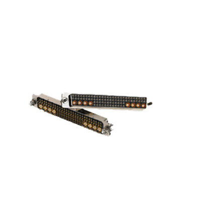
Electrical connectors are key devices that join electrical circuits, equipment, terminal, and application together. Most connectors are removable (a pair with plug and socket) or temporary(removable contacts, pogo pin, insulator, backshell, and shell), but some can be permanent (Sunkye twist pin connector). Connectors make electronic products easier to assemble and manufacture. They also ease circuit repairs and allow flexibility in design and modification. They are used extensively on circuits for communications, industrial machinery, railway, defense system, landing radar, UAV, sensor system, and special field. Sunkye is uniquely qualified to deliver turnkey custom solutions with a complete range of High-Pressure, High-Temperature HPHT electrical connectors.
For the connector industry practitioners, military connectors should not be unfamiliar. We’ve all heard of military style connectors. Do you know how the function of military connectors works? The function of connectors in production is the function of connections. But in other industries, what relevant functions will military connectors play? Let’s talk about this.
In the maintenance industry, especially in the automobile maintenance industry, the use of military style connectors will bring us a lot of help. In the process of maintenance, after using the connector, there is no need to worry about the other operation of the machine, and no need to worry about the other parts of the car stopping because of the repair.
Another function of connectors is that when military connectors are used, they will have different shape design requirements. Each type of connector will have its own application requirements. Of course, in actual use, we can also choose to use some connectors with shape requirements.
Military style connectors will always have different applications in different industries, but in the process of application are different, the main role of connectors in the production process is to connect different production parts. Military connectors play a simple connection role.
Sunkye is a manufacturer specializing in mil grade connector, connector design and production, devoted to connector design and development for more than ten years. It strives to become a leader in the industry, providing customers with competitive solutions and products.
The terminal has three main parts: matching part, transition part and crimping part. The crimping part is the only part whose design is affected by the crimping process. Here are some of the most common problems and corrective actions.
1. Conductor crimping height is too small or too large
Solution: adjust the height of conductor crimping on the crimper. Use vernier calliper or micrometre to check whether the crimping height is within the specified range, and recheck according to the required frequency during the operation to maintain the correct crimping height.
2. The insulation crimping area is too small or too large
Most types of crimping tools can adjust the insulation crimp height. The correct adjustment allows the terminal to clamp the insulation at least 180 degrees without piercing the insulation. When the outer diameter of the insulating crimp of the terminal is close to the outer diameter of the cable insulation, the best method is IDT technology.
3. Loose core
Solution: fold up the cable again to form a bundle, and then insert it into the terminal for crimping. If the removal of the insulation from the cable is a separate operation, the cores may be inadvertently separated during handling or bunching. Use half stripping and keep the insulation removed so that the insulation is not completely removed from the cable until the terminal is ready to be crimped to the cable, which helps to minimize the core looseness.
4. Too short stripping length
The stripping length of the cable is too short, and the distance out of the front of the conductor crimping area cannot obtain the required outer diameter of the cable. The solution is simple: increase the stripping length of the stripping equipment to the specified value of the terminal.
5. The cable is inserted too deep
Solution: make sure that no excessive force is used to insert the cable into the crimper to make it over-voltage the cable stop of the crimper, or adjust the position of the cable stop to correctly position the stripped cable axially.
6. Over bending
Solution: adjust the position of the limit pin on the crimper. This pin is located in the crimper and contacts the joint area of the terminal when crimping the cable in the crimping area. During the crimping process, a large amount of metal at one end of the terminal (in the crimping area) moves. Such a large force tends to force the front of the terminal up unless limited by a suitable “limit pin.”
7. Crimping too far forward
The reason for this problem is that the terminal and the metal strip (the metal strip connected by the terminal when you receive the goods from the manufacturer) are not in the correct position relative to the crimper. Just loosen the base plate of the interchangeable tool, and then realign the crimper to solve the problem.
8. Too small bell mouth
The correct size of the bell mouth is 2 times the thickness of the terminal material. In essence, it affects the performance of the terminal. If the bell mouth is missing or the thickness of the terminal material is less, there is a risk of cutting the wire core. Reduced core retention reduces termination strength. To correct the problem, make sure that the punch on the crimping device is correctly aligned with the base.
9. The bell mouth is too large
If the bell mouth is too large, the total contact area between the terminal crimping area and the cable will be reduced. The smaller the contact surface between the cable and the terminal, the smaller the cable drawing force. If the crimp height is correct, it may be caused by tool wear and should be replaced.
10. Tail material is too long
Solution: adjust the feeding plate on the crimper to make the terminal correctly centred in the crimper. Another sign that the terminals are not properly centred is that the bellmouth is not properly formed. This occurs because the bell mouth has a spatial relationship with the tool of the tailings.
11. Installation of an intelligent pressure management system
The intelligent pressure management system can monitor the operation of the terminal machine in real-time, find out the abnormal pressure in time, and adjust and maintain the equipment in time as described above! In this way, the machine has been in a good state of operation, thus indirectly reducing the production of defective products!
However, it should be noted that although the pressure management is very sensitive and can be used to evaluate the operation of the machine, in normal production, the tolerance is usually set to a large extent to reduce the number of alarms, so the various adverse conditions described above are basically impossible to detect all without leakage.
The intelligent pressure management system can detect 100% of the fatal problems such as all the core wires are cut off, all the glue is wrapped, and the terminals are deformed. These fatal problems cause great pressure changes. It is the main significance to prevent these fatal problems from flowing to customers!
Compared with the outer conductor, the inner conductor with a smaller size and lower strength is more likely to cause poor contact and lead to connector failure. Most of the inner conductors of the connector adopt elastic connection, such as spring claw type elastic connection, socket slotted type elastic connection, bellows-type elastic connection, etc. Among them, the socket slotted elastic connection has the advantages of simple structure, low processing cost, convenient assembly and the most extensive application.
1. The inner conductor is not fixed firmly
In order to assemble, the structure of many RF coaxial connectors is that the inner conductor is divided into two sections by the support of the medium and then connected with the thread. However, due to the small diameter of the inner conductor, the connection strength of the inner conductor is very poor, especially for some small RF coaxial connectors, if the screw connection is not fixed with glue. Therefore, when the connector is connected and disconnected for many times, under the long-term action of torsion and tension, the internal conductor thread may loosen and fall off, leading to connection failure.
One of the common structures of the RF coaxial connector is that the inner conductor, dielectric support and outer conductor are fixed together by adhesive. If the amount of glue applied is not enough or the connection strength of the glue is not enough during the assembly of this structure, the glue applied part may be broken due to the stress during the use, which will cause the inner conductor to rotate or move axially, the inner conductors cannot form good electrical contact, and the connection fails.
Improvement method: when the coaxial connector is assembled, the proper amount of conductive adhesive or thread locking agent can be applied to the threaded connection to increase the reliability of the threaded connection. The adhesive with high bonding strength shall be selected, and the glue shall be filled into the whole glueing hole during glueing; the knurling at the glueing place of the inner conductor shall be increased to increase the contact area between the inner conductor and the adhesive, so as to prevent the inner conductor from rotating; the radial dimensions and tolerances of the inner conductor, the outer conductor and the medium support shall be adjusted properly, so that the fit between the inner conductor and the medium support, the medium support and the outer conductor is interference. Fit also can make the three together more firmly.
2. The size of a socket or pin of the inner conductor is incorrect
If the hole diameter of the conductor in the jack is smaller than the specified size, when the pin of the conductor in the pin enters the jack, it will cause the jack to expand excessively, and the shape variable will exceed its elastic deformation range, resulting in plastic deformation, resulting in damage to the conductor in the jack; on the contrary, if the pin diameter is too small, when the pin and the jack fit, the gap between the pin and the wall of the jack is too large, and the two inside of the connector If the conductor cannot be contacted closely, the contact resistance will increase, and the electrical performance index of the connector will be very poor.
Improvement method: whether the fit of Jack and pin is reasonable or not can be measured by the insertion force and retention force when the standard gauge pin and the conductor in Jack fit. Therefore, we can take the insertion force and retention force as an inspection standard, and adjust the dimensions and tolerances of the jack and the pin, as well as the aging treatment process of the conductor in the jack, so that the insertion force and retention force between the pin and the jack are in a proper range.
USB, the abbreviation of universal serial bus in English, is an external bus standard, which is used to regulate the connection and communication between computers and external devices. It is an interface technology applied in the field of PC.
Universal serial bus (USB) is a new data communication mode which gradually replaces other interface standards. It was jointly developed by Intel, Compaq, digital, IBM, Microsoft, NEC, Northern Telecom and other computer companies and communication companies in 1995, and gradually formed industry standards. As a kind of high-speed serial bus, USB bus’s extremely high transmission speed can meet the application environment requirements of high-speed data transmission, and the bus also has the advantages of simple power supply (bus power supply), convenient installation and configuration (plug and play and hot plug are supported), simple expansion port (127 peripherals can be expanded at most through the hub), diversified transmission modes (4 transmission modes ), as well as the advantages of good compatibility (downward compatibility after product upgrade).
Since its introduction, the universal serial bus has successfully replaced serial port and parallel port and has become one of the standard expansion interfaces and necessary interfaces for a large number of computers and intelligent devices in the 21st century. Now it has developed to USB version 3.2. USB has the advantages of fast transmission speed, convenient use, hotplug support, flexible connection, independent power supply, etc. it can connect a variety of peripherals such as the keyboard, mouse, large-capacity storage device, etc. the interface is also widely used in smartphones. The interaction between intelligent devices such as computers and external data is mainly based on network and USB interface.
1. polarization
The USB connector can only be nominally inserted in one way. It is possible to force a wrong connector, but this can cause damage to the device.
2. At least four contacts
All USB connectors have at least four contacts (some USB models may have five, USB 3.0 connectors or more), which are used for power, ground and two data lines (D + and D -). The USB connector is designed to transmit 5V up to 500mA.
3. shielding
The USB connector is shielded, so it provides a metal shell that does not belong to the circuit, which is very important to keep the signal intact in the environment with a lot of electrical “noise”.
4. Powerful power connection
It is very important for the power pin to establish a connection before the data line to avoid trying to power the device through the data line, which is taken into account in the design of all USB connectors.
5. Mould strain relief
All USB cables are plastic-wrapped at the connector to prevent pressure on the cable and damage to the electrical connection.
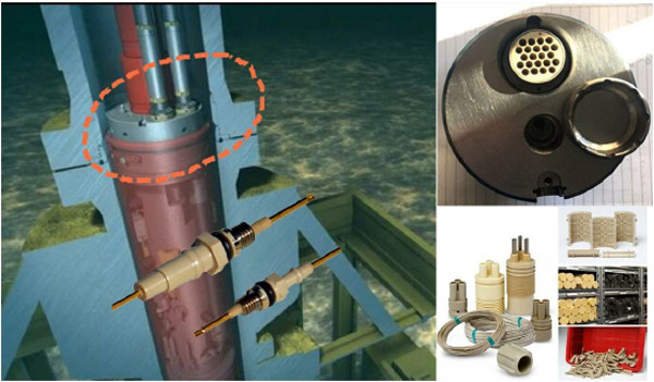
PEEK connector, we also call it PEEK sealing terminal or HTHP connector, just as its name implies which the connector is made from PEEK material combining with metal contact and using glass sintered technology sealing PEEk material & contact so it has perfect air leakage performance. In wellhead, gate valve requires to PEEK terminal for sealing, or tubing head spool for connect gauge or control line of the outlet of the wellhead, and using on adapter spool for hydraulic control line terminated(C/L), electrical cable fit. PEEK connector, we also call it PEEK sealing terminal or HTHP connector, just as its name implies which the connector is made from PEEK material combining with metal contact and using glass sintered technology sealing PEEk material & contact so it has perfect air leakage performance. In wellhead, the gate valve requires to PEEK terminal for sealing, or tubing head spool for the connect gauge or control line of the outlet of the wellhead, and using on adapter spool for hydraulic control line terminated(C/L), electrical cable fit.
The working environment of the oil gas petrochemical industry always is harshness, dirty, high pressure, extreme temperature, chemical corrosion, low PH erosion, and various different kinds of gas. PEEK, benefits of physical performance with Pressure in 30,000PSI /207Mpa, the extreme temperature in 300℃, it satisfies for the special area and high-performance solutions.
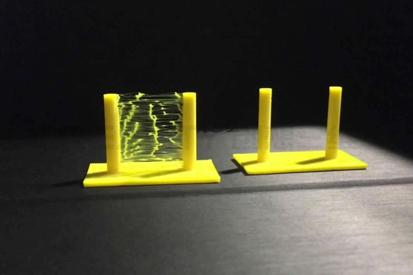
PEEK melts at a relatively high temperature (343°C / 649.4°F) compared to most other thermoplastics. In the range of its melting temperature, it can be processed using injection molding or extrusion methods. It is technically feasible to process granular PEEK into filament form and 3D printing parts from the filament material using fused deposition modeling – FDM (or fused filament fabrication – FFF) technology. PEEK filaments have been demonstrated for producing medical devices up to class IIa. In its solid state PEEK is readily Machinable, for example, by (CNC) milling machines and is commonly used to produce high-quality plastic parts that are thermostable and both electrically and thermally insulating. Filled grades (30% Glass filled) of PEEK can also be CNC machined, but special care must be taken to properly manage stresses in the material. PEEK is considered a high-performance polymer, that is to say, its high price restricts its use to the most demanding applications only.
What is PEEK?
Polyether ether ketone (PEEK) is a colorless organic thermoplastic polymer in the polyaryletherketone (PAEK) family, used in engineering applications.
PEEK is a thermoplastic semicrystalline with excellent mechanical and chemical resistance properties that are retained to high temperatures. PEEK has a glass transition temperature of around 143 °C (289 °F) and melts around 343 °C (662 °F). That’s why PEEK seals and manifolds are commonly used in fluid applications. PEEK also performs well in applications where continuous high temperatures (up to 500 °F/260 °C) are common. It has high resistance to halogen, strong bronsted and Lewis acids, thermal degradation, biodegradation, Air leak: helium leak test ≤ 1× 10 -3 Pa.cm 3 /s
Because of its robustness, PEEK is used to fabricate items used in demanding applications, including bearings, piston parts, pumps, High-performance liquid chromatography columns, compressor plate valves, and electrical cable insulation. It is one of the few plastics compatible with ultra-high vacuum applications.
Beware of the difference of PEEK & PEK;
PEEK is Polyether ether keton & PEK is Polyether keton, both are very strong mechanical and chemical resistance properties but PEEk has one more molecule that means the physical performance more stability.
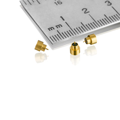
As a specialist in advanced mil spec connectors automotive, Sunkye has extensive experience in micro-miniature and nano miniature solutions based on the highly reliable Twist Pin contact technology. If you want to know more details or want a quotation , just feel free to contact us!
As a specialist in advanced military connectors china, Sunkye has extensive experience in micro-miniature and nano miniature solutions based on the highly reliable Twist Pin contact technology. If you want to know more details or want a quotation , just feel free to contact us!
Domestic D-sub connectors are usually divided into DB, HDB, DP, HDP, DR and HDR. You must have a headache about various types. Today I’ll help you sort out the application of d style connector.
D-sub connector, also known as D-sub miniature, is a common electrical connector in computers. D-sub connector has parallel pin arrangement and is surrounded by metal shield. The shielding end is short, similar to the English letter D. D-sub connectors have been widely used for many years.
D style connector has been used in many applications as multi-channel connector, but the most widely known is for RS-232 serial connection. In fact, D-sub connectors have been used for serial connections on most computers for many years, and today, various types of D-sub connectors can still be found on most computers.
D-sub connectors were originally called sub-miniature connectors and are now commonly referred to as D-sub-miniature connectors. Although these connectors were small when first introduced, they are no longer considered to be truly miniature connectors. D-sub connectors usually consist of two or more parallel connection lines. The connector has a metal housing in D format. This not only provides mechanical strength for connectors, but also provides some limited screening: plug and socket metal housing contact to provide screening. In addition, panel mounting connectors are usually fixed to the panel using nuts with additional threads that allow fit connectors to be fixed to prevent loosening.
As a specialist in advanced mil spec connectors automotive, Sunkye has extensive experience in micro-miniature and nano miniature solutions based on the highly reliable Twist Pin contact technology. If you want to know more details or want a quotation , just feel free to contact us!
Space bio-3D printing from Human Cartilage to Thyroid Gland in Rodents and to Space Artificial Meat: SUNKYE Satisfies the Connection and Signal System of Bio-3D Printing in Micro-gravity Environment
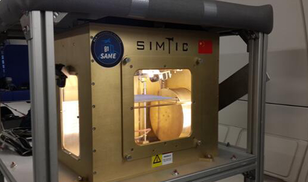
Space bio-3D printing may be a concept we’ve heard recently. But as with 3D printing technology, there was only a short accumulation before it happened! Do we need Space bio-3D printing? Can’t we perform such a complex task on Earth? Of course, the answer is yes. But research on pace bio-3D printing shows that it may be more effective in a micro-gravity environment. Meanwhile, decades of exploration of other planets will require bio-printing onboard ships to cure astronauts’ diseases.
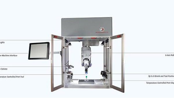
The International Space Station will be the best place to conduct such exercises. In 2018, Russian astronaut Oleg Kononenko became the first person to make Space biometric 3D printing on behalf of his country. Using a 3D printer created for the space environment, Kononenko can produce human cartilage tissue and rodent thyroid glands. The bio-3D printing engineering experiment with the cooperation of the United States, Russia and Israel began in September 2019. On October 7, 2019, Aleph Farms, Israel’s biotechnology startup, announced that it had conducted a joint experiment on the International Space Station on September 26 to successfully cultivate the first piece of artificial meat in space using a three-dimensional bio-printer. The experiment was conducted by Aleph Farms in collaboration with the Russian Biotechnology Laboratory 3D Bio-Printing Solutions and two American companies. The experiment content is to deliver bovine cells to the International Space Station and then grow them into small muscle tissues similar to traditional meat in a microgravity environment using a 3D bio-printer.
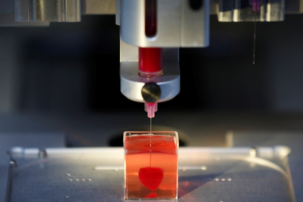
With 3D printing becoming the mainstream, bio-printing has become the core focus in the medical field, showing the potential of unlimited innovation opportunities. The environment is the key to the development of fragile cells. Even in the best research laboratories, fragile cells are usually not easy to maintain. By pressing the material in the syringe for biological printing, the cells can grow in different forms. In October 2017, the mission aboard Soyuz MS-10 failed, but the printer was eventually delivered to the International Space Station.
Researchers are curious about how microgravity can facilitate bioprinting and the growth of cells and tissues. At the same time, the recent use of this technology in space to examine other medical problems has also interested them, such as radiation and human problems. At present, the focus of the research is on how the structures are combined and how they behave. So the connection system and signal transmission are required to have a precise system and a lighter volume.
Sunkye Space Micro Connector & Nano Connector Series Environment Performance
Vibration
10Hz-2000Hz 294m2/s
Random Vibration Power
Power spectral density 0.6G /Hz, root mean 2 square value of total acceleration 28.4G
Shock
980m/s2 6ms
Salt spray
96h
Humidity
240h
Thrmal shock
-55 to +175°C
Environment temperature range
-55 to +175°C
Magnetic permeability
200 gamma
Irradiation resistant
Total dose:1X10⁶ Gy
Thermal vacuum outgassing
TML ≤ 1% , CVCM ≤ 0.1%
Scientists around the world have created organizations to carry out further medical research, which continues to make progress in bioprinting. The ultimate goal includes the manufacture of human organs in the laboratory. Such innovations could have a huge impact on patients with severe illnesses, such as those waiting for organ donations. Besides, 3D printing organs offer the possibility of patient-specific nursing, which may mean that people do not have to worry about infection, rejection and severe complications.
Space 3D printing technology will play an indispensable role in future space station operation, deep space exploration and other tasks. As far as we know, it takes at least half a year for the space station to wait for the replenishment of the Earth, while 3-D printing takes only 1-2 days to produce parts that need to be replaced. Therefore, it is helpful for astronauts to manufacture necessary experimental tools, maintenance tools and spare parts under a weightlessness environment. It greatly improves the flexibility of space station experiment and the timeliness of maintenance, reduces the types and quantity of space station spare parts and operating costs, and reduces the dependence of space station on ground replenishment. And China’s first space on-orbit 3D printer has already been developed successfully.Chongqing Institute of Green and Intelligent Technology of the Chinese Academy of Sciences announced that after two years of efforts, the first domestic 3D printer developed by the Institute and the Center of Space Application Engineering Technology of the Chinese Academy of Sciences has successfully completed parabolic weightlessness flight test in Bordeaux, France, and can complete 3D printing in microgravity environment.
Company Info:
Sunkye International Co., Ltd
Flat/RM, 1402B 14/F The Belgian Bank Building, Nos. 721-725 Nathan Road Mongkok HK.
As a specialist in advanced military connectors china, Sunkye has extensive experience in micro-miniature and nano miniature solutions based on the highly reliable Twist Pin contact technology. If you want to know more details or want a quotation , just feel free to contact us!
There are many kinds of micro miniature coaxial connectors: SMA, SMB, SMC, APC-7, K connector, etc. This article will give you an interpretation.
Whatever connector you use, you need to pay attention to its applicable frequency range before using it. The frequency range of the connector is limited by the first circular waveguide propagation mode in the coaxial structure. Reducing the diameter of the outer conductor will increase the maximum usable frequency. Filling the space with insulators reduces the maximum usable frequency and increases system losses. The performance of all connectors is affected by the quality of the connector interface. If the diameter of inner and outer conductors deviates from the design requirements, the quality of electroplating is poor, or the gap between the joints is large, the reflection coefficient and resistance loss of the interface will be reduced. This is why in the same kind of connector, the one with good quality, can be used at higher frequencies and has smaller standing wave coefficients.
If the circuit you need to measure and test is below 18GHz, you can choose SMA connector, N connector and APC-7 connector. You can choose the specific type, according to your circuit type, cost and so on. If you have enough money, you can also use K connector, etc. If you measure and test in millimeter wave band, you can choose K connector or 2.4mm connector. Why not choose a 3.5mm connector? Because compared with K-connector, it has neither price advantage nor performance advantage (the applicable frequency is not as high as K-connector).
As a specialist in advanced mil spec connectors automotive, Sunkye has extensive experience in micro-miniature and nano miniature solutions based on the highly reliable Twist Pin contact technology. If you want to know more details or want a quotation , just feel free to contact us!